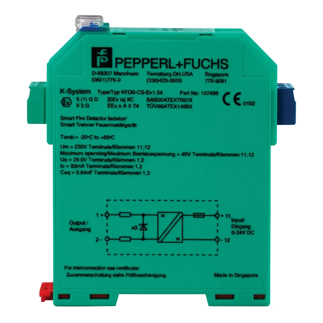
Apollo XP95 I.S. Galvanic Barrier
£346.65 (inc VAT: £415.98)
Summary
The XP95 Intrinsically Safe (I.S.) Galvanic Barrier is a specialised interface device designed for intrinsic safety applications in hazardous environments. This sophisticated barrier provides reliable control and signal transfer to XP95 compatible fire and smoke alarm transmitters operating inside hazardous areas, ensuring safe operation in potentially explosive atmospheres.
As a loop-powered device, the XP95 I.S. Galvanic Barrier eliminates the need for separate power supplies, simplifying installation whilst maintaining the highest safety standards. The unit achieves SIL3 certification according to IEC 61508, making it suitable for the most demanding safety-critical applications. With comprehensive international approvals including ATEX, IECEx, FM and UL certifications, this galvanic barrier delivers proven performance for protecting personnel and assets in Zone 0, 1 and 2 hazardous locations.
Features
- Single channel isolated barrier for intrinsically safe applications
- Loop-powered operation eliminates need for separate power supply
- Compatible with XP95 fire and smoke alarm transmitters
- Safety integrity level up to SIL3 according to IEC 61508
- Analogue input signal type with 4-20V DC transmission range
- Safe electrical isolation between input and output circuits
- Compact DIN rail mounting design (20 x 107 x 115 mm)
- Wide operating temperature range from -20°C to 60°C
- IP20 degree of protection with screw terminal connections
- ATEX certified for Zone 0, 1 and 2 hazardous areas
- IECEx, FM and UL international approvals
- Low power dissipation of less than 0.2W
- Fast response time under 50 microseconds
- Suitable for both gas and dust hazardous atmospheres
FAQ
What is the XP95 I.S. Galvanic Barrier used for?
The XP95 I.S. Galvanic Barrier is used for intrinsic safety applications where fire and smoke detection is required in hazardous areas. It provides a safe interface for control and signal transfer to XP95 compatible alarm transmitters operating inside potentially explosive atmospheres, ensuring reliable fire detection whilst maintaining intrinsic safety requirements.
Does the barrier require a separate power supply?
No, the XP95 I.S. Galvanic Barrier is loop-powered, which means it draws its power from the fire alarm control loop itself. This eliminates the need for separate power supplies and simplifies installation. However, it’s important to verify using the technical data that proper voltage is available to the field devices.
What safety certification does the barrier hold?
The XP95 I.S. Galvanic Barrier achieves Safety Integrity Level 3 (SIL3) certification according to IEC 61508, representing the highest level of safety performance for single-channel devices. It also holds ATEX certification for European markets, IECEx approval for international applications, and FM/UL approvals for North American installations.
What hazardous area zones is the barrier approved for?
The barrier is approved for use in Zone 0, Zone 1 and Zone 2 hazardous gas atmospheres, as well as dust environments. It carries the marking [Ex ia Ga] IIC for gas and [Ex ia Da] IIC for dust applications, making it suitable for the most stringent hazardous area classifications where continuous or frequent explosive atmospheres may be present.
How is the XP95 I.S. Galvanic Barrier installed?
The barrier is designed for simple installation on standard 35mm DIN mounting rail according to EN 60715:2001. It features removable screw terminal connections for field and control circuits, with clear terminal identification. The compact dimensions of 20 x 107 x 115 mm allow for space-efficient installation in control panels and junction boxes.
What is the operating temperature range?
The XP95 I.S. Galvanic Barrier operates reliably across an ambient temperature range of -20°C to 60°C (-4°F to 140°F), making it suitable for both indoor and outdoor installations in various climatic conditions where hazardous atmospheres may exist.
Specifications
- Part Number: 29600-098
- Signal Type: Analogue input
- Safety Integrity Level: SIL3 (acc. to IEC 61508)
- Rated Voltage: Loop powered
- Power Dissipation: < 0.2 W for Uin = 24 V Io = 20 mA
- Control Circuit Terminals: 11+, 12-
- Control Circuit Voltage: 0 – 24 V
- Control Circuit Current: 0 – 20 mA
- Field Circuit Terminals: 1+, 2-
- Short-Circuit Current: < 65 mA
- Transmission Range Voltage: 4 – 20 V dc/0 – 6 Vppac
- Transmission Range Current: 1 – 20 mA
- Deviation After Calibration: < 3.5 mA current loss at 20 mA load current
- Temperature Influence: ± 20 µA/K
- Rise Time/Fall Time: < 50 µs (load current > 1 mA)
- Galvanic Isolation: Safe electrical isolation acc. to IEC/EN60079-11, voltage peak value 375 V
- Ambient Temperature: -20 to 60°C (-4 to 140°F)
- Degree Of Protection: IP20
- Connection Type: Screw terminals
- Mass: Approx. 100g
- Dimensions: 20 x 107 x 115 mm (0.8 x 4.2 x 4.5 inch), housing type B1
- Mounting: 35 mm DIN mounting rail acc. to EN 60715:2001
- Eu-Type Examination Certificate: BAS 00 ATEX 7087
- Atex Marking: II (1)GD, I (M1) [Ex ia Ga] IIC, [Ex ia Da] IIC, [Ex ia Ma] I
- Voltage Uo: 28 V
- Current Io: 93 mA
- Power Po: 653 mW
- Maximum Safe Voltage Um: 253 V
- Type Of Protection: [Ex ia]
- Iecex Approval: IECEx BAS 08.0079, IECEx BAS 10.0007X
- Fm Approval: Control drawing 116-0129 (cFMus)
- Ul Approval: Control drawing 116-0348 (cULus)
- Emc Directive: 2014/30/EU EN61326-1:2013 (industrial locations)
- Atex Directive: 2014/34/EU EN 60079-0:2012+A11:2013, EN 60079-11:2012, EN 60079-15:2010
Downloads
- Datasheet (Adobe PDF)
Additional information
| Weight | 1 kg |
|---|