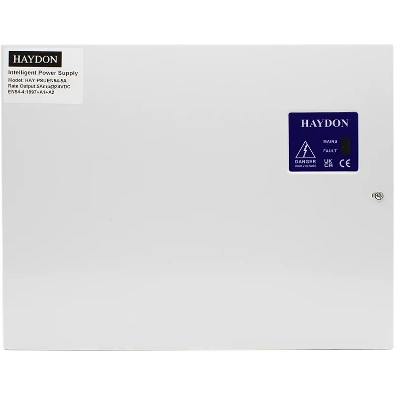
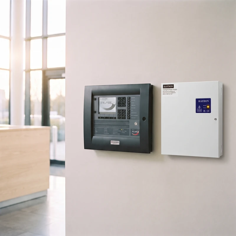
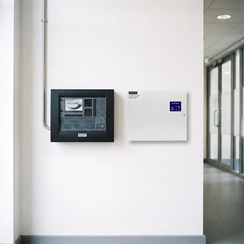

Haydon HAY-PSUEN54-5A EN54-4 Power Supply | 24V DC, 5A, Small Enclosure
£127.45 (inc VAT: £152.94)
You may also need


Key features
- Five-code amber diagnostic LED for fault finding
- 5A continuous output for larger auxiliary loads
- Separate GEN and EPS volt-free fault outputs
Downloads
Summary
The Haydon HAY-PSUEN54-5A is a 27.6VDC uninterruptible power supply built to feed auxiliary devices on a fire alarm system, and what sets it apart on the bench is its built-in diagnostic LED, which gives you five distinct fault codes rather than a single generic warning light. That means you can read the amber LED and know straight away whether you’re looking at a blown fuse, a missing battery, a charging fault or a failed temperature sensor.
View full overview Show less
On a commercial install that saves you a return visit and gives you something concrete to report back to the client or main contractor. You get the diagnosis on site, first time, instead of swapping parts to find the fault by elimination.
Inside the small steel enclosure the unit houses 2 x 7Ah batteries and switches to battery standby automatically if mains power is lost, maintaining output to keep connected fire devices running. Two-stage charging and temperature-compensated charging voltage keep those batteries in good condition between services, so you’re not called back for premature battery failure.
Features
- 5A rated output - power a larger run of auxiliary fire devices from a single PSU
- Amber diagnostic LED - five fault codes let you pinpoint the issue on site without test gear
- GEN and EPS volt-free outputs - report general fault and mains loss status back to a panel or BMS
- Two-stage battery charging - bulk charges to 80% within 24 hours then floats to 100% within 48 hours
- Deep discharge protection - disconnects batteries below 21V to prevent damage from over-draining
- Overload protection circuit - protects the PCB from damage during a short circuit or overload on the output
- Temperature-compensated charging - adjusts charging voltage with ambient temperature to extend battery life
- Compliant to EN54-4:1997+A1+A2 for use on fire detection and alarm systems
Specifications
| Rated Voltage Frequency | 110-240V AC, 47-63Hz |
|---|---|
| Input Current | 1.2A |
| Mains Fuse Rating | F3A |
| Output Voltage Mains Power | 22.0-27.6 Vdc |
| Output Voltage Battery Standby | 20.0-26.0 Vdc |
| Ripple | <150 mV |
| Output Fuse | F5A |
| Battery Fuse | F5A |
| Imax With Charging | 5A |
| Imax No Charging | 5.8A |
| Battery Capacity | 2 x 7Ah |
| Ri Max | 5Ω maximum internal resistance of battery and circuitry |
| I Min | 0.1A |
| Battery Charging | Two stage - bulk charge to 80% within 24 hours, float charge to 100% within 48 hours |
| Constant Current Charge | 0.8A |
| Temperature Compensation | -30mV/°C (0-50°C) |
| Low Battery Voltage Trigger | 23V |
| Deep Discharge Protection Cut Out | 21V |
| GEN Fault Output | Normally closed, 0.50A @ 60Vdc, 0.9Ω solid state relay, volt free; opens if mains failed and battery under 23V, or fault condition |
| EPS Fault Output | Normally closed, 0.50A @ 60Vdc, 0.9Ω solid state relay, volt free; opens if loss of mains for over 10 seconds |
| Operating Temperature | -20°C to +45°C, 20-90% RH non-condensing |
| Storage Temperature | -25°C to +85°C, 10-90% RH non-condensing |
| Enclosure Material | 1.2mm steel, white powder coated |
| Enclosure Dimensions WxHxD | 275 x 330 x 80mm |
| Weight Excluding Batteries | 3.3kg |
| Weight With Batteries Fitted | Approximately 8kg |
| Approvals | EN54-4:1997+A1+A2, EMC 2014/30/EU, LVD 2014/35/EU, RoHS2.0 2011/65/EU, Environmental Class II |
FAQ
This model is built for the small enclosure and houses 2 x 7Ah sealed lead acid batteries connected in series using the supplied bridging wire. If your standby time calculation needs more capacity than 7Ah batteries can provide, you’ll need to check whether a larger enclosure variant suits the job instead. No. The datasheet specifies these are volt-free relay contacts rated 0.50A at 60Vdc, so any circuit you connect them to must stay below 60Vdc. On initial power-up with no batteries or temperature sensor connected, the yellow fault LED will flash continuously - this is expected and not a fault. Once the batteries and temperature sensor leads are connected and the system is retested, the LED should stop flashing after a few seconds. Haydon’s recommended minimum for the 5A output PSU is 0.75mm² cable, with earth fitted if required. Mains cable should also be a minimum of 0.75mm² with an earth connection. Disconnect one of the battery leads and the yellow fault LED should begin flashing within a minute, with the amber diagnostic LED showing two flashes as per the fault-finding guide. Reconnect the batteries and both LEDs should stop flashing after a few seconds, confirming correct connection. Yes, the PSU should be connected to a dedicated mains circuit with a Mains Isolation Switch labelled ‘FIRE ALARM - MAINS POWER ISOLATION SWITCH’, fused at a maximum of 5 amps.What battery capacity does the HAY-PSUEN54-5A take?
Can the GEN and EPS outputs be wired into a 230V circuit?
Why is the yellow fault LED still flashing after I've powered it up?
What cable size should I use for the output wiring?
How do I know if the batteries are correctly connected during commissioning?
Does this unit need a dedicated mains supply?
Downloads
- Datasheet (Adobe PDF)
Additional information
| Output Current | 5A |
|---|---|
| Device Type | |
| Battery Charging | Yes |
| Maximum Batteries | 2 × 7Ah |
| Colour | |
| Mounting | Surface |
| Fault Relay / LED |