VESDA-E VEA 40 Relay Local STAX
£1,650.00 (inc VAT: £1,980.00)
Summary
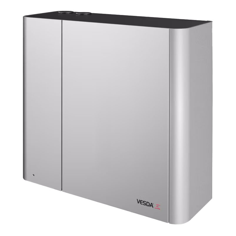
The VESDA-E VEA 40-Relay Local StaX (VER-A40-40-STX) is a purpose-built accessory that extends the addressability capabilities of the VESDA-E VEA detector system by providing individual relay outputs for precise alarm location signalling. This intelligent relay expansion module enables fire alarm control panels to receive specific location information as secondary reporting, complementing the primary Fire 1 relay connection that remains mandatory for main alarm reporting.
Each Relay StaX unit provides 40 individual relay connections that correspond directly to the 40 addressable sampling tubes on a VEA detector, delivering full addressability for enhanced fire source localization. When the VEA detector identifies smoke at specific sampling points during its sequential scanning process, the corresponding relays activate to provide precise location information to connected fire alarm systems or building management systems.
The system offers exceptional scalability, with each VEA detector capable of powering and controlling up to three Relay StaX units, enabling comprehensive coverage for large installations. The robust IP40-rated enclosure matches the VEA detector dimensions for seamless installation either above or below the main detector unit. Additionally, the enclosure provides convenient mounting space for fire panel loop input modules, streamlining system integration while maintaining the clean, professional installation appearance that characterizes the VESDA-E product family.
Features
- 40 individual relay outputs corresponding to each VEA detector sampling tube
- Direct one-to-one mapping with relays 1-40 corresponding to tubes 1-40
- Each relay responds to smoke events located on specific detector tubes
- Configurable relay latching follows detector alarm latching configuration
- Secondary alarm location reporting while maintaining mandatory primary Fire 1 relay connection
- Expandable system supports up to three Relay StaX units per VEA detector
- Direct power and control from connected VEA detector
- Integrated mounting provision for fire panel loop input modules within enclosure
- Robust IP40-rated enclosure for reliable protection
- Identical dimensions to VEA detector for seamless installation alignment
- Flexible mounting options above or below the main detector unit
- Precision mounting spacer for exact bracket alignment with detector
- Same spacer accommodates direct wall mounting installations
- Easy installation with optional steel support bracket
- Comprehensive Xtralis VSC software support for commissioning and maintenance
- Programmable relay contacts rated 2A @ 30 VDC resistive
- Low power consumption with 20mA quiescent and 250mA average alarm current
- Wide operating temperature range 0°C to 38°C (32°F to 100°F)
- Operating humidity tolerance 5% to 95% RH non-condensing
- Four cable entry points with 25mm cable access
- Screw terminal blocks for secure cable termination (0.2-1.5 sq mm, 24-16 AWG)
- Professional appearance matching VEA detector housing design
- Automatic relay activation during VEA detector scanning sequence
- Enhanced fire source localisation for faster emergency response
- Streamlined integration with existing fire alarm control panels
- Reliable secondary reporting system for critical applications
- Field-proven compatibility with VEA detector addressability system
FAQ
How does the Relay StaX integrate with the VEA detector system?
The Relay StaX is directly powered and controlled by the VEA detector, requiring no separate power supply. When the VEA detector detects smoke and performs its sequential scanning to identify affected tubes, the Relay StaX automatically activates the corresponding relay for each tube where smoke is found. The relay mapping is direct: relays 1-40 correspond to tubes 1-40 on the detector, providing precise location information.
Can multiple Relay StaX units be connected to one VEA detector?
Yes, each VEA detector can power and control up to three Relay StaX units, providing a total of 120 individual relay outputs when fully expanded. This scalability enables comprehensive addressability coverage for large installations while maintaining the one-to-one correspondence between relays and sampling tube locations across multiple StaX units.
Is the primary Fire 1 relay connection still required when using Relay StaX?
Yes, it is mandatory to connect the Fire 1 relay wiring to the Fire Alarm Control Panel (FACP) for primary alarm reporting. The Relay StaX provides secondary reporting information for location identification, but does not replace the primary alarm notification requirements. This ensures compliance with fire safety regulations while adding enhanced location capabilities.
How are the Relay StaX units physically installed?
The Relay StaX features the same dimensions as the VEA detector and can be mounted above or below the detector unit. A precision spacer is provided to exactly align the Relay StaX mounting bracket with the detector mounting bracket. The same spacer accommodates direct wall mounting if preferred. The installation is straightforward with optional steel support brackets and maintains a professional, integrated appearance.
How does the relay latching behaviour work?
The Local Relay StaX relay latching follows the detector’s alarm latching configuration automatically. This means the relay behaviour (latching or non-latching) is determined by how the VEA detector is configured, ensuring consistent alarm handling across the entire system without requiring separate configuration of the Relay StaX unit.
What fire panel integration options does the Relay StaX provide?
The Relay StaX enclosure provides mounting space for fire panel loop input modules inside the unit, enabling clean integration with various fire alarm control panels. Each of the 40 relay outputs can be connected to monitor inputs on fire panels, providing precise zone identification. The 2A @ 30 VDC rated contacts are suitable for most fire panel input requirements, and the system supports both latching and non-latching configurations as needed.
Specifications
- Supply Voltage : 18 to 30 VDC (24 VDC Nominal)
- Power Consumption Average Quiescent : 20 mA
- Power Consumption Average Alarm : 250 mA
- Dimensions (W H D) : 352.05 mm x 340.5 mm x 135.5 mm (13.9 in x 13.4 in x 5.3 in)
- Weight : 5.1 kg (11.22 lbs)
- Operating Temperature Ambient : 0°C to 38°C (32°F to 100°F)
- Operating Humidity : 5% to 95% RH, non-condensing
- Storage Temperature (Non-Operational) : 0° to 85°C
- Storage Humidity (Non-Operational) : Dry (<95%)
- Storage Conditions : Must not be exposed to sunlight or other radiation sources
- Number Of Relays : 40 individual relay outputs
- Relay Contact Rating : 2A @ 30 VDC (Resistive)
- Relay Configuration : Programmable to latch or not latch
- Relay Mapping : Relays 1 to 40 correspond to tubes 1 to 40 for the detector
- Maximum Relay StaX Per Detector : Up to 3 units
- Power Source : Direct power and control from VEA detector
- IP Rating : IP40 (not UL tested)
- Cable Access : 4 x 25 mm (1″) cable entries
- Cable Termination : Screw terminal blocks (0.2-1.5 sq mm, 24-16 AWG)
- Mounting Options : Above or below detector, optional steel support bracket
- Mounting Spacer : Provided for precise alignment with detector mounting bracket
- Fire Panel Integration : Mounting provision for loop modules inside enclosure
- Software Support : Xtralis VSC software package for commissioning and maintenance
- Relay Latching Behaviour : Follows detector alarm latching configuration
- Enclosure Material : IP40-rated robust construction
- Primary Alarm Requirement : Mandatory Fire 1 relay connection to FACP maintained
- Secondary Reporting : Individual relay outputs for precise location signalling
Downloads
- Datasheet (Adobe PDF)
Additional information
| Weight | 3 kg |
|---|