Kentec Syncro View Local LCD Repeater Panel
Summary
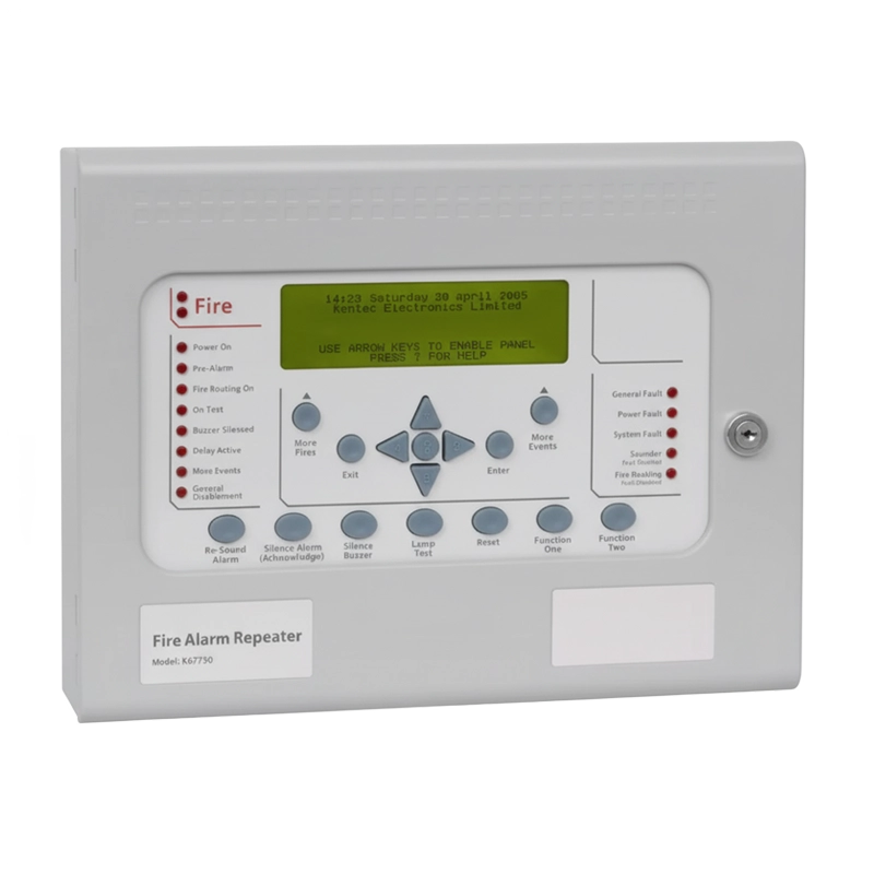
The Syncro View fire alarm repeater panel provides a cost-effective, simple and convenient method of extending the controls and indications of the Syncro AS fire alarm control panel to additional locations throughout a building. This compact LCD repeater offers a smaller, more aesthetic alternative to installing multiple full-sized control panels where only indication and basic control functionality is required at remote locations.
Featuring a large graphic LCD display (240 x 64 pixels), high brightness LED indicators, and a complete set of controls that duplicate the functionality of the main Syncro AS fire alarm control panel, the Syncro View enables effective fire system management from up to 15 additional locations. The repeater connects via a simple two-wire serial data connection (separate to the Syncro AS network), utilizing RS485 protocol with support for cable runs up to 1200 metres total length, making it practical for large buildings and multi-floor installations.
The Syncro View is designed for environmental class A indoor use and housed in a robust 1.2mm mild steel enclosure with IP30 rating and epoxy powder coating. Available in multiple configurations, the repeater offers either 24V DC power (which can be powered via the Syncro AS control panel’s auxiliary 24V DC supply using just two additional cores) or 230V AC power with local battery backup. Models are also available with or without an enable control keyswitch, providing flexibility for different access control requirements. With removable electronics for easy installation, low power consumption, multi-language support, and connection monitoring by the main fire control panel, the Syncro View delivers reliable remote indication and control for professional fire alarm systems. The unit also features 3 programmable inputs and 5 programmable relay outputs, providing additional control integration options for complex fire safety installations.
Features
- Up to 15 annunciators can be connected to each Syncro AS panel
- Compatible with Response or Syncro AS fire control panels
- Large liquid crystal display: 240 x 64 pixels graphic LCD
- 8 lines of 40 characters display capability
- High brightness LED indications for clear status visibility
- Internal sounder for local audible alerting
- Replicates all Syncro panel controls and indications
- Simple two-wire serial RS485 connection
- Up to 1200 metres total cable length supported
- Small, compact enclosure: 330 x 255 x 90mm
- Removable electronics for easy installation and maintenance
- 24V DC or 230V AC power options available
- 24V DC models can be powered from Syncro panel auxiliary supply
- 230V AC models include local battery backup
- Two 12V 1.9Ah sealed lead acid batteries in series
- Low power consumption: 0.03A quiescent current in mains fail
- Multi-language display options
- Connection monitored by Syncro fire control panel
- Fault indication if repeater disconnected or communication lost
- 3 programmable inputs for system integration
- 5 programmable relay outputs for control functions
- Individual addressing via 4-way DIL switch (addresses 1-15)
- Data termination jumper for end-of-line units
- Processor and watchdog reset switches included
- COMMS LED indicates communication status
- Maximum 4 units can be powered from single Syncro Aux 24V output
- Models available with or without enable control keyswitch
- Robust 1.2mm mild steel construction
- IP30 rated enclosure
- Epoxy powder coated finish
- 5 x 20mm cable entry knockouts in top and 5 in rear
- Environmental class A: -5°C to +40°C operating temperature
- Maximum 95% relative humidity non-condensing
- Surface or flush mounting options available
- Configuration via Loop Explorer utility software
- Buzzer synchronization with host panel (V5.90+ firmware)
FAQs
How many Syncro View repeaters can be connected to a single fire alarm panel?
Up to 15 Syncro View repeaters can be connected to each Syncro AS fire alarm control panel via the serial data bus. Each unit must be assigned a unique address (1-15) using the 4-way DIL switch on the circuit board. The maximum total cable length for all repeaters is 1200 metres using 2-core RS485 shielded fire alarm cable. Each repeater’s connection is monitored by the control panel, which will indicate a fault condition if any configured repeater becomes disconnected.
What is the difference between 24V DC and 230V AC powered models?
The 24V DC models (K67000M1, K67001M1) require external 24V DC power, which can be conveniently supplied from the main Syncro panel’s auxiliary 24V output using just two additional cable cores alongside the data connection. Up to 4 repeaters can be powered from a single Syncro panel auxiliary output. The 230V AC models (K67750M1, K67751M1) include an internal 750mA power supply and battery backup (two 12V 1.9Ah sealed lead acid batteries), providing complete standalone power with backup in case of mains failure. Choose 24V DC models for simpler installation when panels are relatively close, or 230V AC models for locations requiring independent battery backup or when the auxiliary supply capacity would be exceeded.
What is the enable control keyswitch and when should I specify it?
Models K67001M1 (24V DC) and K67751M1 (230V AC) include an enable control keyswitch on the fascia, while models K67000M1 and K67750M1 do not. The enable control keyswitch provides an additional layer of security by requiring a key to be turned before the repeater’s control functions (such as Silence, Reset, Test, etc.) become active. This is useful in locations where you want to provide status indication to a wider audience but restrict control operations to authorized personnel only. Without the keyswitch, all controls are immediately accessible to anyone at the repeater location. Choose keyswitch models for public areas or locations requiring controlled access to fire system functions.
How does the Syncro View handle communication and what happens if communication is lost?
The Syncro View communicates with the main Syncro panel via a two-wire RS485 serial data connection, separate from the Syncro AS network. The COMMS LED on the circuit board flashes quickly when communication is active and working correctly, and goes off if the unit is disconnected or connected incorrectly. The main Syncro panel continuously monitors each configured repeater’s connection. If a Syncro View that should be present (as configured in Loop Explorer) loses communication or is disconnected, the main panel will indicate a fault condition. This ensures any communication problems are immediately detected and reported, maintaining system integrity.
How do I add a Syncro View repeater to my existing Syncro system?
Adding a Syncro View requires both physical installation and system configuration. First, install the unit with appropriate fire alarm cable (shielded cable like FP200 with metal glands), connecting the two data cores to the COMMS terminals on the main panel and power cores to the AUX 24V terminals (for 24V models) or local mains supply (for 230V models). Set a unique address using the 4-way DIL switch on the PCB. Then use the Loop Explorer configuration utility to add the View repeater to your system: click the site name, double-click the View Repeater icon, select the panel it connects to, and configure its name (location) and address. The address set in software must match the physical DIL switch setting. Once the configuration is loaded into the panel, the panel will monitor for the repeater’s presence and indicate faults if it’s not connected or communication is lost.
What is the data termination jumper and when should it be removed?
All Syncro View repeaters are supplied with a jumper fitted at position J3 on the left side of the PCB. This jumper connects a terminating resistor that must be present at the last unit on the data line to ensure proper RS485 communication. If you’re installing only one repeater, leave the jumper in place. If you’re installing multiple repeaters, you must remove the jumpers from all units except the last one in the daisy-chain connection. The termination resistor at the end of the line is essential for reliable serial communication – incorrect termination can cause communication errors or intermittent operation across all repeaters on the bus.
Specifications
- Product Name: Syncro View Serial LCD Repeater Panel
- Compatible Panels: Syncro AS, Response fire control panels
- Model K67000M1: Syncro View repeater panel (24V DC)
- Model K67750M1: Syncro View repeater panel with 750mA PSU (230V AC)
- Model K67001M1: Syncro View repeater panel with enable keyswitch (24V DC)
- Model K67751M1: Syncro View repeater panel with enable keyswitch and 750mA PSU (230V AC)
- Construction: 1.2mm mild sheet steel (18SWG)
- IP Rating: IP30
- Finish: Epoxy powder coated
- Colour – Lid & Box: BS 00 A 05 grey – fine texture
- Colour – Controls Plate & Labels: RAL 7047 light grey – satin
- Weight: 4kg (standard panel), 5kg maximum
- Dimensions (W X H X D): 330 x 255 x 90mm
- Mounting Options: Surface or flush mount
- Display Type: Graphic LCD
- Display Size: 240 x 64 pixels
- Display Capacity: 8 lines of 40 characters
- LED Indicators: High brightness LEDs
- Internal Sounder: Yes
- Cable Entry: 5 x 20mm knockouts in top, 5 in rear, 1 in side
- Mains Supply (Mains Powered Models): 230V AC +10% -15% (20 Watts maximum)
- 24V Supply (24V DC Models): 21 to 30V DC
- Mains Supply Fuse (Mains Models): 2 Amp, 20mm, glass HRC
- Power Supply Rating (Mains Models): 28V 750mA total (including battery charging)
- Maximum Ripple Voltage (Mains Models): 200 millivolts
- Battery Type (Mains Models): Two 12 Volt 1.9Ah sealed lead acid (Yuasa NP) in series
- Battery Charge Voltage (Mains Models): 27.6VDC nominal
- Battery Charge Current (Mains Models): 0.2A (200mA) maximum
- Battery Fuse (Mains Models): 200 milliamp, 20mm, glass
- Maximum Current Draw From Batteries (Mains Models): 0.095 Amps (95mA)
- Quiescent Current In Mains Fail: 0.03A (30mA)
- Serial Data Connection: 2 core RS485
- Maximum Cable Length: Up to 1200 metres total
- Maximum Data Cable Resistance: 25 ohms per core
- Cable Type Required: Shielded fire alarm cable (e.g. FP200) with metal glands
- Maximum Terminal Capacity: 2.5mm²
- Max Number Of Units Per Panel Serial Bus: 15
- Maximum Units Powered From Syncro Aux 24V: 4
- Addressing Method: 4-way DIL switch (binary addresses 1-15)
- Data Termination: Push-on jumper at J3 (fit on last unit only)
- Programmable Inputs: 3
- Programmable Relay Outputs: 5
- Environmental Class: A (indoor use only)
- Operating Temperature: -5°C (+/- 3) to +40°C (+/- 2)
- Maximum Relative Humidity: 95% non-condensing
- Multi-Language Support: Yes
- Connection Monitoring: Monitored by Syncro fire control panel
- Configuration Method: Loop Explorer utility software
- Processor Reset: Manual switch provided
- Watchdog Reset: Manual switch provided
- Communication Status LED: COMMS LED (flashes when communicating)
- Buzzer Synchronization: With host panel (Syncro V5.90+, Syncro AS V5.22+)
- Document Reference: Man-1092 Issue 07 May 2016
- Datasheet Reference: DS43/09/17
- Manufacturer: Kentec Electronics Ltd
Additional information
| Weight | 0.5 kg |
|---|---|
| Control Enable Key | No, Yes |
| 750mA PSU | No, Yes |