


Linear heat detection in car parks: an application guide

Why linear heat detection cable (LHDC) is the detection method of choice for car parks, how to choose between analogue and digital systems, and how to design and install it to BS 5839-1.
At a glance
- Car parks defeat conventional smoke detectors: high airflow, exhaust fumes, damp and humidity cause false alarms and delayed activation. LHDC is unaffected by all of them.
- A single LHDC zone can cover 1,600 m² to 2,000 m², in line with BS 5839-1, and connects to a conventional or analogue addressable fire alarm panel like any other zone.
- Two system types: analogue (resettable) for sites that want to reset after an event, and digital (non-resettable) for longer runs and lower cost.
- Runs are spaced at a maximum of 10.6 m centres (5.3 m either side of the cable), fixed with an air gap so the ceiling cannot act as a heat sink.
- The cable is discreet, has a small bend radius for awkward layouts, and is far less exposed to vandalism than point detectors.
1. Why car parks are a hard environment for fire detection
Car park fires are getting more severe, not less. Modern vehicle construction uses more combustible materials, so a single vehicle fire can generate intense heat, reach very high temperatures and spread quickly to neighbouring vehicles, adjacent floors and connected buildings. In an enclosed or multi-storey structure, confined space makes both evacuation and firefighting harder, and structural damage between floors is a real risk.
The detection system has to do two jobs at once: protect life, and protect the building and its infrastructure. Fast, reliable detection reduces damage, cuts the cost and downtime of repair, and limits the spread of toxic fumes and pollution.
The problem is that the environment works against most detectors. Car parks typically have:
A detection system that generates unwanted alarms in a car park quickly loses credibility with the building operator, and a system that needs frequent maintenance in a fume-laden environment becomes an ongoing cost. Both undermine the reason the system was installed.
2. Why linear heat detection cable suits car parks
Linear heat detection cable (LHDC) is a continuous sensing cable that detects abnormal heat along its entire length, rather than at discrete points. In a car park that changes the picture:
- Unaffected by airflow and exhaust gases. LHDC responds to heat, not smoke, so ventilation and vehicle fumes have no effect on its performance.
- Unaffected by damp and humidity. The cable is designed for harsh environments, which removes the main source of unwanted alarms from smoke-based systems.
- Total area coverage, even in difficult layouts. The small bend radius lets the cable follow ramps, split levels and irregular bays without leaving gaps.
- Low maintenance, low vandalism risk. A cable fixed to the soffit is discreet and has no exposed sensing head. Where extra mechanical protection is needed, a braided version of the cable is available.
- Early warning of overheating as well as fire. LHDC detects abnormal heat before flame develops, giving the building a head start on response.
The result is a system that protects people, vehicles and structure without the compromise on reliability that smoke detection forces in this environment.
3. What makes up the system
Patol offers two LHDC systems for car parks. Both share the same basic building blocks, all of which are available from Huvo:
- Control device — monitors the cable and reports alarm and fault conditions to the fire alarm panel. Required for analogue systems; optional for digital cable, but recommended where you want EN 54-28 compliance, fault monitoring or a distance display.
- Linear heat detection cable — installed on the ceiling or on a dedicated cable tray in parallel runs across the protected area. Both cable types are available with a stainless steel braid for extra mechanical protection.
- End of line (EOL) terminator — terminates each zone so the control device can monitor the cable for open circuit and short circuit faults. Versions with a fire and fault test key switch make routine testing straightforward.
- Fixings and accessories — stainless steel L brackets, P clips with neoprene insulators, stainless cable ties and junction boxes for interposing cable or through connections.
Each zone sends an alarm signal back to its control device, which in turn connects to a conventional fire alarm panel or integrates fully with an analogue addressable system. The LHDC zone therefore behaves like any other detection zone on the panel, and can be linked to sprinklers or suppression systems where the fire strategy calls for it.

4. Analogue or digital: choosing the right cable
| Analogue (resettable) | Digital (non-resettable) | |
|---|---|---|
| Maximum zone length | Up to 300 m | Up to 2 km (1,999 m) |
| Detection behaviour | Hot spot on a small section of cable, plus ambient temperature rise across the whole zone | Hot spot on a very small section of cable at a fixed trigger temperature |
| After an alarm | Cable recovers and resets | Activated section must be replaced |
| Alarm temperature | Adjustable set point on the controller | Fixed: 70°C, 90°C or 180°C cable options |
| Control device | LDM-519-LP or LDM-519-SEN-N (required) | LDM-519-DIM-28 (interface) or LDM-621-DDL (interface with 2 km distance display) |
| Best suited to | Sites that want to reset without replacing cable; smaller zones | Long single runs; harsh conditions; cost-sensitive projects |
Analogue (resettable)
Patol resettable analogue LHDC is a low smoke zero halogen (LSZH) cable used with the LDM-519-LP controller. This is a loop-powered, SIL 2 certified device with an adjustable alarm set point. It monitors the cable for short circuit and open circuit faults via the EOL terminator, and can be integrated on either a conventional panel or an analogue addressable system. Where two alarm levels are wanted — a pre-alarm and a fire alarm, for example — the LDM-519-SEN-N offers two-level set points.
Zones of up to 300 m can be installed, and the system triggers on both a localised hot spot and a general rise in ambient temperature across the zone. Because the cable is resettable, the system can be returned to service after an activation without replacing cable.
Digital (non-resettable)
Patol digital LHDC supports much longer single zones — up to 2 km — and triggers on hot spots occurring on very small sections of the cable at a fixed alarm temperature. It is available with 70°C, 90°C or 180°C trigger points, with or without stainless steel braid. It is particularly suited to harsh environmental conditions and is the simpler, more cost-effective option, but the activated section of cable is not reusable after an alarm.
Two controller options cover most car park designs:
- LDM-519-DIM-28 — a DIN rail-mounted digital interface module that is EN 54-28:2016 compliant and SIL 2 certified. Specify this where the fire strategy needs certified fault monitoring of the cable but no distance readout.
- LDM-621-DDL — a digital interface with a 2 km distance locator. On a fire condition it displays the distance into the zone at which the alarm occurred, monitors the cable for open circuit faults, and gives LED indication of fire, fault and supply status. It includes an adjustment to allow for interposing cable between the controller and the start of the sensing cable, and is available in standard, galvanic isolator and Zener barrier versions.
Both controllers can be housed in Patol’s key-lockable IP65 enclosure, which is worth specifying in a car park where the controller may be mounted in a damp or exposed position.
Which to specify: if the operator expects occasional activations and wants to reset without a cable replacement visit, analogue is the safer choice. If the priority is long runs, simplicity and cost, and the site accepts that an activated section is replaced after an event, digital is the better fit. On a large multi-storey site, the distance display on the DDL is worth having for fire service response. Choose the digital cable’s alarm temperature to suit the ambient conditions — a car park roof deck in summer needs more headroom than an underground level.
5. Designing the layout
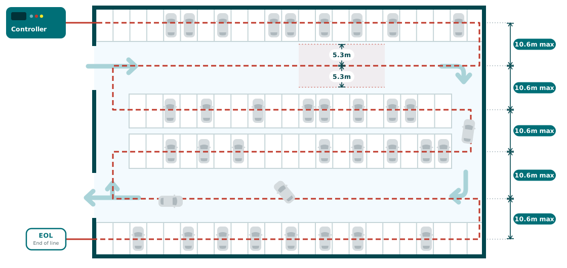
LHDC is designed and zoned to BS 5839-1 (fire detection and fire alarm systems for buildings — non-domestic premises), in the same way as any other heat detection.
- Confirm the system category. Establish with the responsible person and the fire strategy whether the car park requires life protection (L category), property protection (P category) or both, and whether the detection needs to trigger other systems such as smoke ventilation, sprinklers or suppression. This determines what the LHDC output has to do.
- Divide the area into zones. A single LHDC zone can cover between 1,600 m² and 2,000 m² in accordance with BS 5839-1. Split larger floor plates into multiple zones so that an alarm is located to a manageable area.
- Set the run spacing. The cable is installed in parallel runs at a maximum spacing of 10.6 m between runs, giving 5.3 m coverage either side of the cable centre. Reduce spacing where the ceiling geometry, downstand beams or ramps would otherwise leave areas beyond 5.3 m of cable.
- Route around obstructions. Use the cable’s small bend radius to follow the actual layout — around columns, down ramps and through split levels — rather than leaving coverage gaps at awkward points.
- Check zone lengths against the cable type. Keep analogue zones within 300 m of cable and digital zones within 2 km, including any interposing cable back to the controller.
- Decide on cable protection. Where the cable is within reach or exposed to impact, specify braided LHDC for additional mechanical strength.
6. Installation
- Fix to the ceiling or a dedicated cable tray using Patol’s stainless steel fixings: L brackets (30, 70 or 210 mm) to create the stand-off, P clips with neoprene insulators to hold the cable, and stainless cable ties on tray. Do not improvise with generic plastic clips.
- Maintain an air gap. The cable must stand off the ceiling or tray so that the structure does not act as a heat sink and delay the cable’s response. This is the single most common installation error with LHDC, and it is what the L bracket and insulated P clip are for.
- Run in parallel at the spacing set in the design, keeping runs consistent across the floor plate.
- Join and interpose with the right boxes. Use the Patol junction box in its through-connector version to join lengths of sensing cable, and the interposing-cable version where the sensing cable transitions to a standard cable back to the controller.
- Terminate each zone with the correct EOL terminator — analogue or digital (DDL/DIM28) — so the controller can supervise the cable for open and short circuit faults. The test key switch versions let the maintenance engineer simulate fire and fault from the end of the zone without disturbing the cable.
- Connect the controller (LDM-519-LP or SEN-N for analogue; LDM-519-DIM-28 or LDM-621-DDL for digital) to the fire alarm panel as a conventional zone or via the addressable loop, as designed. Mount it in the IP65 enclosure where the location is damp or exposed.
- Set the interposing cable adjustment on the DDL where there is a length of non-sensing cable between the controller and the start of the LHDC, so that the distance display reads correctly.
- Test and commission each zone, recording the zone length, cable type, alarm temperature or set point, and controller settings on the as-installed drawings for the maintenance file.
7. Common pitfalls
- Cable clipped tight to the slab. Without an air gap the concrete draws heat away from the cable and slows detection. Always use the specified stand-off fixings.
- Runs spaced too widely on the drawing, then stretched further on site. Anything beyond 5.3 m from the cable centre is uncovered. Check spacing against the as-built ceiling, not the architect’s plan.
- Zone lengths that ignore the interposing cable. The run from controller to the first sensing cable counts. Digital installations with a DDL need the adjustment set or the distance display will be wrong.
- Treating digital cable as reusable. After an activation the affected section is replaced. Make sure the operator understands this before specifying digital over analogue.
- Forgetting the interface to other systems. If the fire strategy relies on LHDC to start smoke ventilation or suppression, that cause-and-effect needs to be designed, wired and tested, not assumed.